Sunday, 28 May 2017

HOW TO BE A SUCCESSFUL PERSON

 This is a very common thing amongst us now, in this era we are funded with technology and resources all around by one simple thing THE INTERNET.

But, there is something ,some habits that decides whether we are gonna achieve our goal or not.

So, a short answer for the question
BRING YOUR DREAMS , YOUR    IDEA   IN ACTION RIGHT NOW

But, how before coming up with idea there were no problem, there was no distraction, no disturbance. Then why is there problem bringing your idea's to action.

The answer is WE HUMANS . We have made such a complex world that now it is bringing problems to us .

I know there might be several REASONS for not bringing your dreams, the innovative idea's live. I too have faced that problem , but then I have to found a solution to it and I did.   

Look it is not necessay to wake up early and hang up late night as shown it movies and TV.  Just make your own schedule and make up your mind. Bring down the laziness if not you  will never be successful person

SUCCESS IS JUDGED BY THE WORLD, BUT SATISFCATION IS JUDGED BY YOUR MIND BY YOU.

SO try to be happy with whatever you do and never sompare yourself with other.
IF YOU FOUND WHAT YOU DO BRING YOU HAPPINESS YOU ARE ABOUT TO BE SUCCESSFUL
What the intellegent person do you cannot but what you can do even they cannot .

We all are smart at our own level of thinking capability. Just stay YOU 
feel free .

BUT HOW TO BE FREE-
Simple it is - MAKE YOUR MIND LIMITLESS . WHAT YOU FEED YOUR  MIND, IS WHAT YOU THINK AND WHAT YOU THINK IS WHAT YOU DO.  

HOW TO BECOME LIMITLESS- 
There are various videos over YouTube one channel named as Be Inspired 
just go there once, and you feel motivated at next level. A level you have never feeled before.


AT LAST HERE IS YOUR ANSWER . BUT REMEMBER YOUR HABITS REVEALS YOUR ACTIONS AND ACTIONS REVEALS YOUR FUTURE .
MIND YOUR HABITS

HERE IS YOUR ANSWER.


  1. Start planing - How are you gonna bring you dream come true, make a path a roadway or anyway you wan't just start building it. Then comes the next step
  2. Make a dairy - Maintain a book ( or dairy, or a journal) in which you will list up each detail you need to make you project . Just write it down , if you do so then you will have a better idea as to where is the fault and how to overcome it. remeber dont leave a single detail of your project and don't make it messy 
  3. Try to find sponsorhip- This is very important thing beacuse once you started to earn your living, then you wouldn't be able to concentrate over your project. so start to find a sponsorer like parents or do a small job somewhere , such that it will give you enough money to fund your project.
  4. Estimate your time - This is very very very important thing, as you got to manage your time suppose you are studying and you got a idea if it's innovative you have to manage your time such that balanced amount of time is given to your studies, project, friends, family,etc. 
  5. Estimate your material requirement and overall cost of project- Once you have achieved all, those steps earlier you got to estimate price of the whole project and what material you required to carry the project. 
  6. Start the project- Star the project, bring the first process of building it in action as per listed in your diary ( step 1). If yo think that your project need more labour work don't hesitate to bring more people in it . Don't think that if I brought more people in my project they may take the advantage and name it by themselves and I would get no credit . Don't even think of it  why ?  beacuse whatever is goona happen it's already be written in your destiny 
  7. Let the world know about your project- If the world would is not aware   about your project, then whats the deal for making it. Let people know the creator of the invention. Who knows one day you will get attention of someone and you would get hired by him/her.
BUT REMEMBER- NEVER BRING EGO, ATTITUDE, OVER-CONFINDENCE IN YOUR WORK OR ELSE IT WILL BE THE DOOMS DAY OF YOUR PROJECT AND YOU YOURSELF WILL BE THE REASON OF IT.

SO BRING YOUR DREAMS OUT IN ACTION , MAKE IT YOUR PASSION, LIVE IT AND ONE DAY YOUR PASSION WILL BE THE REASON OF YOUR LIVING  


Saturday, 15 April 2017

TELEVISION HYPNOTESIS YOU

Nervous system manipulation by electromagnetic fields from monitors 
US 6506148 B2
ABSTRACT

Physiological effects have been observed in a human subject in response to stimulation of the skin with weak electromagnetic fields that are pulsed with certain frequencies near ½ Hz or 2.4 Hz, such as to excite a sensory resonance. Many computer monitors and TV tubes, when displaying pulsed images, emit pulsed electromagnetic fields of sufficient amplitudes to cause such excitation. It is therefore possible to manipulate the nervous system of a subject by pulsing images displayed on a nearby computer monitor or TV set. For the latter, the image pulsing may be imbedded in the program material, or it may be overlaid by modulating a video stream, either as an RF signal or as a video signal. The image displayed on a computer monitor may be pulsed effectively by a simple computer program. For certain monitors, pulsed electromagnetic fields capable of exciting sensory resonances in nearby subjects may be generated even as the displayed images are pulsed with subliminal intensity.
BACKGROUND OF THE INVENTION
The invention relates to the stimulation of the human nervous system by an electromagnetic field applied externally to the body. A neurological effect of external electric fields has been mentioned by Wiener (1958), in a discussion of the bunching of brain waves through nonlinear interactions. The electric field was arranged to provide “a direct electrical driving of the brain”. Wiener describes the field as set up by a 10 Hz alternating voltage of 400 V applied in a room between ceiling and ground. Brennan (1992) describes in U.S. Pat. No. 5,169,380 an apparatus for alleviating disruptions in circadian rythms of a mammal, in which an alternating electric field is applied across the head of the subject by two electrodes placed a short distance from the skin.
A device involving a field electrode as well as a contact electrode is the “Graham Potentializer” mentioned by Hutchison (1991). This relaxation device uses motion, light and sound as well as an alternating electric field applied mainly to the head. The contact electrode is a metal bar in Ohmic contact with the bare feet of the subject, and the field electrode is a hemispherical metal headpiece placed several inches from the subject's head.
In these three electric stimulation methods the external electric field is applied predominantly to the head, so that electric currents are induced in the brain in the physical manner governed by electrodynamics. Such currents can be largely avoided by applying the field not to the head, but rather to skin areas away from the head. Certain cutaneous receptors may then be stimulated and they would provide a signal input into the brain along the natural pathways of afferent nerves. It has been found that, indeed, physiological effects can be induced in this manner by very weak electric fields, if they are pulsed with a frequency near ½ Hz. The observed effects include ptosis of the eyelids, relaxation, drowziness, the feeling of pressure at a centered spot on the lower edge of the brow, seeing moving patterns of dark purple and greenish yellow with the eyes closed, a tonic smile, a tense feeling in the stomach, sudden loose stool, and sexual excitement, depending on the precise frequency used, and the skin area to which the field is applied. The sharp frequency dependence suggests involvement of a resonance mechanism.
It has been found that the resonance can be excited not only by externally applied pulsed electric fields, as discussed in U.S. Pat. Nos. 5,782,874, 5,899,922, 6,081,744, and 6,167,304, but also by pulsed magnetic fields, as described in U.S. Pat. Nos. 5,935,054 and 6,238,333, by weak heat pulses applied to the skin, as discussed in U.S. Pat. Nos. 5,800,481 and 6,091,994, and by subliminal acoustic pulses, as described in U.S. Pat. No. 6,017,302. Since the resonance is excited through sensory pathways, it is called a sensory resonance. In addition to the resonance near ½ Hz, a sensory resonance has been found near 2.4 Hz. The latter is characterized by the slowing of certain cortical processes, as discussed in the '481, '922, '302, '744, '944, and '304 patents.
The excitation of sensory resonances through weak heat pulses applied to the skin provides a clue about what is going on neurologically. Cutaneous temperature-sensing receptors are known to fire spontaneously. These nerves spike somewhat randomly around an average rate that depends on skin temperature. Weak heat pulses delivered to the skin in periodic fashion will therefore cause a slight frequency modulation (fm) in the spike patterns generated by the nerves. Since stimulation through other sensory modalities results in similar physiological effects, it is believed that frequency modulation of spontaneous afferent neural spiking patterns occurs there as well.
It is instructive to apply this notion to the stimulation by weak electric field pulses administered to the skin. The externally generated fields induce electric current pulses in the underlying tissue, but the current density is much too small for firing an otherwise quiescent nerve. However, in experiments with adapting stretch receptors of the crayfish, Terzuolo and Bullock (1956) have observed that very small electric fields can suffice for modulating the firing of already active nerves. Such a modulation may occur in the electric field stimulation under discussion.
Further understanding may be gained by considering the electric charges that accumulate on the skin as a result of the induced tissue currents. Ignoring thermodynamics, one would expect the accumulated polarization charges to be confined strictly to the outer surface of the skin. But charge density is caused by a slight excess in positive or negative ions, and thermal motion distributes the ions through a thin layer. This implies that the externally applied electric field actually penetrates a short distance into the tissue, instead of stopping abruptly at the outer skin surface. In this manner a considerable fraction of the applied field may be brought to bear on some cutaneous nerve endings, so that a slight modulation of the type noted by Terzuolo and Bullock may indeed occur.
The mentioned physiological effects are observed only when the strength of the electric field on the skin lies in a certain range, called the effective intensity window. There also is a bulk effect, in that weaker fields suffice when the field is applied to a larger skin area. These effects are discussed in detail in the '922 patent.
Since the spontaneous spiking of the nerves is rather random and the frequency modulation induced by the pulsed field is very shallow, the signal to noise ratio (S/N) for the fm signal contained in the spike trains along the afferent nerves is so small as to make recovery of the fm signal from a single nerve fiber impossibile. But application of the field over a large skin area causes simultaneous stimulation of many cutaneous nerves, and the fm modulation is then coherent from nerve to nerve. Therefore, if the afferent signals are somehow summed in the brain, the fm modulations add while the spikes from different nerves mix and interlace. In this manner the S/N can be increased by appropriate neural processing. The matter is discussed in detail in the '874 patent. Another increase in sensitivity is due to involving a resonance mechanism, wherein considerable neural circuit oscillations can result from weak excitations.
An easily detectable physiological effect of an excited ½ Hz sensory resonance is ptosis of the eyelids. As discussed in the '922 patent, the ptosis test involves first closing the eyes about half way. Holding this eyelid position, the eyes are rolled upward, while giving up voluntary control of the eyelids. The eyelid position is then determined by the state of the autonomic nervous system. Furthermore, the pressure excerted on the eyeballs by the partially closed eyelids increases parasympathetic activity. The eyelid position thereby becomes somewhat labile, as manifested by a slight flutter. The labile state is sensitive to very small shifts in autonomic state. The ptosis influences the extent to which the pupil is hooded by the eyelid, and thus how much light is admitted to the eye. Hence, the depth of the ptosis is seen by the subject, and can be graded on a scale from 0 to 10.
In the initial stages of the excitation of the ½ Hz sensory resonance, a downward drift is detected in the ptosis frequency, defined as the stimulation frequency for which maximum ptosis is obtained. This drift is believed to be caused by changes in the chemical milieu of the resonating neural circuits. It is thought that the resonance causes perturbations of chemical concentrations somewhere in the brain, and that these perturbations spread by diffusion to nearby resonating circuits. This effect, called “chemical detuning”, can be so strong that ptosis is lost altogether when the stimulation frequency is kept constant in the initial stages of the excitation. Since the stimulation then falls somewhat out of tune, the resonance decreases in amplitude and chemical detuning eventually diminishes. This causes the ptosis frequency to shift back up, so that the stimulation is more in tune and the ptosis can develop again. As a result, for fixed stimulation frequencies in a certain range, the ptosis slowly cycles with a frequency of several minutes. The matter is discussed in the '302 patent.
The stimulation frequencies at which specific physiological effects occur depend somewhat on the autonomic nervous system state, and probably on the endocrine state as well.
Weak magnetic fields that are pulsed with a sensory resonance frequency can induce the same physiological effects as pulsed electric fields. Unlike the latter however, the magnetic fields penetrate biological tissue with nearly undiminished strength. Eddy currents in the tissue drive electric charges to the skin, where the charge distributions are subject to thermal smearing in much the same way as in electric field stimulation, so that the same physiological effects develop. Details are discussed in the '054 patent.
SUMMARY
Computer monotors and TV monitors can be made to emit weak low-frequency electromagnetic fields merely by pulsing the intensity of displayed images. Experiments have shown that the ½ Hz sensory resonance can be excited in this manner in a subject near the monitor. The 2.4 Hz sensory resonance can also be excited in this fashion. Hence, a TV monitor or computer monitor can be used to manipulate the nervous system of nearby people.
The implementations of the invention are adapted to the source of video stream that drives the monitor, be it a computer program, a TV broadcast, a video tape or a digital video disc (DVD).
For a computer monitor, the image pulses can be produced by a suitable computer program. The pulse frequency may be controlled through keyboard input, so that the subject can tune to an individual sensory resonance frequency. The pulse amplitude can be controlled as well in this manner. A program written in Visual Basic(R) is particularly suitable for use on computers that run the Windows 95(R) or Windows 98(R) operating system. The structure of such a program is described. Production of periodic pulses requires an accurate timing procedure. Such a procedure is constructed from the GetTimeCount function available in the Application Program Interface (API) of the Windows operating system, together with an extrapolation procedure that improves the timing accuracy.
Pulse variability can be introduced through software, for the purpose of thwarting habituation of the nervous system to the field stimulation, or when the precise resonance frequency is not known. The variability may be a pseudo-random variation within a narrow interval, or it can take the form of a frequency or amplitude sweep in time. The pulse variability may be under control of the subject.
The program that causes a monitor to display a pulsing image may be run on a remote computer that is connected to the user computer by a link; the latter may partly belong to a network, which may be the Internet.
For a TV monitor, the image pulsing may be inherent in the video stream as it flows from the video source, or else the stream may be modulated such as to overlay the pulsing. In the first case, a live TV broadcast can be arranged to have the feature imbedded simply by slightly pulsing the illumination of the scene that is being broadcast. This method can of course also be used in making movies and recording video tapes and DVDs.
Video tapes can be edited such as to overlay the pulsing by means of modulating hardware. A simple modulator is discussed wherein the luminance signal of composite video is pulsed without affecting the chroma signal. The same effect may be introduced at the consumer end, by modulating the video stream that is produced by the video source. A DVD can be edited through software, by introducing pulse-like variations in the digital RGB signals. Image intensity pulses can be overlaid onto the analog component video output of a DVD player by modulating the luminance signal component. Before entering the TV set, a television signal can be modulated such as to cause pulsing of the image intensity by means of a variable delay line that is connected to a pulse generator.
Certain monitors can emit electromagnetic field pulses that excite a sensory resonance in a nearby subject, through image pulses that are so weak as to be subliminal. This is unfortunate since it opens a way for mischievous application of the invention, whereby people are exposed unknowingly to manipulation of their nervous systems for someone else's purposes. Such application would be unethical and is of course not advocated. It is mentioned here in order to alert the public to the possibility of covert abuse that may occur while being online, or while watching TV, a video, or a DVD.
DESCRIPTION OF THE DRAWINGS
FIG. 1 illustrates the electromagnetic field that emanates from a monitor when the video signal is modulated such as to cause pulses in image intensity, and a nearby subject who is exposed to the field.

FIG. 2 shows a circuit for modulation of a composite video signal for the purpose of pulsing the image intensity.
FIG. 3 shows the circuit for a simple pulse generator.

FIG. 4 illustrates how a pulsed electromagnetic field can be generated with a computer monitor.
FIG. 5 shows a pulsed electromagnetic field that is generated by a television set through modulation of the RF signal input to the TV.

FIG. 6 outlines the structure of a computer program for producing a pulsed image.


FIG. 7 shows an extrapolation procedure introduced for improving timing accuracy of the program of FIG. 6.
FIG. 8 illustrates the action of the extrapolation procedure of FIG. 7.


FIG. 9 shows a subject exposed to a pulsed electromagnetic field emanating from a monitor which is responsive to a program running on a remote computer via a link that involves the Internet.
FIG. 10 shows the block diagram of a circuit for frequency wobbling of a TV signal for the purpose of pulsing the intensity of the image displayed on a TV monitor.
FIG. 11 depicts schematically a recording medium in the form of a video tape with recorded data, and the attribute of the signal that causes the intensity of the displayed image to be pulsed.

FIG. 12 illustrates how image pulsing can be embedded in a video signal by pulsing the illumination of the scene that is being recorded.
FIG. 13 shows a routine that introduces pulse variability into the computer program of FIG. 6.
FIG. 14 shows schematically how a CRT emits an electromagnetic field when the displayed image is pulsed.
FIG. 15 shows how the intensity of the image displayed on a monitor can be pulsed through the brightness control terminal of the monitor.
FIG. 16 illustrates the action of the polarization disc that serves as a model for grounded conductors in the back of a CRT screen.
FIG. 17 shows the circuit for overlaying image intensity pulses on a DVD output.


FIG. 18 shows measured data for pulsed electric fields emitted by two different CRT type monitors, and a comparison with theory.

CLAIMS BY FIRST PATENT OWNER 
I claim:
1. A method for manipulating the nervous system of a subject located near a monitor, the monitor emitting an electromagnetic field when displaying an image by virtue of the physical display process, the subject having a sensory resonance frequency, the method comprising:
creating a video signal for displaying an image on the monitor, the image having an intensity;
modulating the video signal for pulsing the image intensity with a frequency in the range 0.1 Hz to 15 Hz; and
setting the pulse frequency to the resonance frequency.
2. A computer program for manipulating the nervous system of a subject located near a monitor, the monitor emitting an electromagnetic field when displaying an image by virtue of the physical display process, the subject having cutaneous nerves that fire spontaneously and have spiking patterns, the computer program comprising:
a display routine for displaying an image on the monitor, the image having an intensity;
a pulse routine for pulsing the image intensity with a frequency in the range 0.1 Hz to 15 Hz; and
a frequency routine that can be internally controlled by the subject, for setting the frequency;
whereby the emitted electromagnetic field is pulsed, the cutaneous nerves are exposed to the pulsed electromagnetic field, and the spiking patterns of the nerves acquire a frequency modulation.
3. The computer program of claim 2, wherein the pulsing has an amplitude and the program further comprises an amplitude routine for control of the amplitude by the subject.
4. The computer program of claim 2, wherein the pulse routine comprises:
a timing procedure for timing the pulsing; and
an extrapolation procedure for improving the accuracy of the timing procedure.
5. The computer program of claim 2, further comprising a variability routine for introducing variability in the pulsing.
6. Hardware means for manipulating the nervous system of a subject located near a monitor, the monitor being responsive to a video stream and emitting an electromagnetic field when displaying an image by virtue of the physical display process, the image having an intensity, the subject having cutaneous nerves that fire spontaneously and have spiking patterns, the hardware means comprising:
pulse generator for generating voltage pulses;
means, responsive to the voltage pulses, for modulating the video stream to pulse the image intensity;
whereby the emitted electromagnetic field is pulsed, the cutaneous nerves are exposed to the pulsed electromagnetic field, and the spiking patterns of the nerves acquire a frequency modulation.
7. The hardware means of claim 6, wherein the video stream is a composite video signal that has a pseudo-dc level, and the means for modulating the video stream comprise means for pulsing the pseudo-dc level.
8. The hardware means of claim 6, wherein the video stream is a television broadcast signal, and the means for modulating the video stream comprise means for frequency wobbling of the television broadcast signal.
9. The hardware means of claim 6, wherein the monitor has a brightness adjustment terminal, and the means for modulating the video stream comprise a connection from the pulse generator to the brightness adjustment terminal.
10. A source of video stream for manipulating the nervous system of a subject located near a monitor, the monitor emitting an electromagnetic field when displaying an image by virtue of the physical display process, the subject having cutaneous nerves that fire spontaneously and have spiking patterns, the source of video stream comprising:
means for defining an image on the monitor, the image having an intensity; and
means for subliminally pulsing the image intensity with a frequency in the range 0.1 Hz to 15 Hz;
whereby the emitted electromagnetic field is pulsed, the cutaneous nerves are exposed to the pulsed electromagnetic field, and the spiking patterns of the nerves acquire a frequency modulation.
11. The source of video stream of claim 10 wherein the source is a recording medium that has recorded data, and the means for subliminally pulsing the image intensity comprise an attribute of the recorded data.
12. The source of video stream of claim 10 wherein the source is a computer program, and the means for subliminally pulsing the image intensity comprise a pulse routine.
13. The source of video stream of claim 10 wherein the source is a recording of a physical scene, and the means for subliminally pulsing the image intensity comprise:
pulse generator for generating voltage pulses;
light source for illuminating the scene, the light source having a power level; and
modulation means, responsive to the voltage pulses, for pulsing the power level.
14. The source of video stream of claim 10, wherein the source is a DVD, the video stream comprises a luminance signal and a chrominance signal, and the means for subliminal pulsing of the image intensity comprise means for pulsing the luminance sign

How Did America Get Its Name?

The global population currently sits at just over 7.4 billion people, and nearly all of them have heard of the United States of America. As a dominant superpower for the past century, the shortened version – America – can stir pride, admiration, fear, envy, or distrust in the minds of people in every corner of the globe. However, as every child in America learns, the country was first discovered by Christopher Columbus in 1492.
So why isn’t the country named Columba?

The Strange Tale of Amerigo Vespucci

The exploits of Christopher Columbus are well known to most school-children, and even the name Amerigo Vespucci is widely circulated through international culture, but the exact details of the latter legend are usually unknown, and the two men’s relationship is often viewed as a mystery.
Amerigo Vespucci was an Italian explorer, cartographer and navigator that also made a number of trips across the Atlantic, just like Christopher Columbus. However, prior to that, he worked in the commercial house of the Medici family in Florence, and helped to manage financing and supplies for a number of expeditions across the ocean, including some of Columbus’ later voyages. While Columbus initially had a monopoly on expeditions to the West Indies, by 1495, other navigators were granted licenses to explore the new area of “India”.
Now, it is important to remember that Christopher Columbus, despite landing in the Bahamas in 1492, believed for more than a decade that he had found a western route to India. Even after numerous expeditions to parts of the Caribbean and America, he remained certain that he had made his way to Asia.
1bnj5r
Over his years of service in the mercantile industry of Europe, Vespucci had earned respect and built connections across the continent. He was eventually invited by King Manuel I of Portugal to join an expedition across the ocean, which would eventually explore the southern coast of this “new continent”. Between 1499 and 1502, roughly 7-10 years after Columbus’ legendary voyages, Vespucci found that the southern coast of “India” went much further south than previously thought.
During the 1499 trek, he and his company explored the northern part of South America, and reached the Amazon River. At that point, he falsely believed that he was in India, just like Columbus. There was some anecdotal evidence – and a potentially forged letter – that Vespucci had actually been on an earlier expedition in 1497 that reached Central America. If this were true, that means that Vespucci had actually reached the mainland of the Americas before Christopher Columbus!
1bnisz

Given the unproven nature of those claims, historians agree that Vespucci’s 1501 expedition is where he solidified his reputation as a legendary explorer. On this trip, he traveled down the southern coast of south America, past present-day Rio de Janeiro, all the way to within 400 miles of the continents southern tip.
At this point, he was confident that his expedition (as well as Columbus’ before him) had not actually reached India, but a completely new continent, one that was not part of the “Old World” (Europe, Asia and Africa).

Amerigo’s Rise to Fame

During his series of expeditions, Amerigo Vespucci wrote numerous letters back to colleagues and friends in Europe, describing the places he had been and the wonders he had seen. Furthermore, he wrote books about his travels once he returned, both in 1502 and 1504, in which he referred to Central, South and North America as “Novus Mundi” (translated as “The New World”).
Amerigo Vespucci was the first to claim and essentially prove that the land mass he, John Cabot and Christopher Columbus had all explored was not India, but rather a completely unknown continent. His writings were vivid and entertaining, and caught the attention of publishers and citizens across Europe. These books were reprinted in dozens on European languages, and his accounts became some of the best sources for information on the New World. Christopher Columbus, on the other hand, had never written publicly about his “discovery”, but had continued to claim that he had landed in India.
Five years later, Martin Waldseemüller, a German cartographer, made a map of this exciting new world, and used Vespucci’s writings as the main source material for their topographic information. When they published the map, they placed the word AMERICA across the land mass, honoring the navigator to whom they attributed the discovery. Within 30 years, present-day North America had been added to that New World Map, and cartographers attributed the name America to that part of the continent as well. The rest, as they say is history.

An Alternate Explanation?

While historians and scholar have reached a general consensus on Amerigo Vespucci as the namesake of America, there is another explanation cited by some. While Columbus and Vespucci get much of the credit for early discoveries of the New World, English fishermen had been in Newfoundland, high on the northeastern coast of the continent, decades earlier.
A man named Richard Amerike, a wealthy English merchant from Bristol, was also a senior member of the Fellowship of Merchants and a customs officer. Trade records have shown that in 1481, Amerike shipped a load of salt (in order to salt fish) to these early sailors/fishermen. The belief is that those sailors named the region in which they were fishing after their sponsor – Amerike.
1bnjhm
Furthermore, Richard Amerike was reputed to own the ship, the Matthew, which carried the expedition of John Cabot to Newfoundland in 1497. The belief is that Cabot named the territory where he landed America, and included that name on an early map.
In the early 20th century, the idea that America was actually named in honor of this man, Richard Amerike, was raised in academic circles. Letters in the Spanish National archives show that Columbus had received a copy of this earlier map, complete with the name “Amerike” on the land mass. Unlike the Italian explorers, who were eager to claim international credit for their discovery, the Bristol sailors and merchants were interested in keeping their lucrative fishing grounds a secret, which is why this alternative theory of America’s name has rarely been considered.
We may never know the real origin of America’s name, but these are certainly the leading contenders.  In the eyes of the majority of the world, Amerigo Vespucci’s name will go down in history, while Christopher Columbus will retain the exploratory glory!

Why Do Helicopters Have A Tail Rotor?

We all might be having doubt as to why is a small blade fitted over the tail of a helicopter.
Now without stretching time heres a short answer.

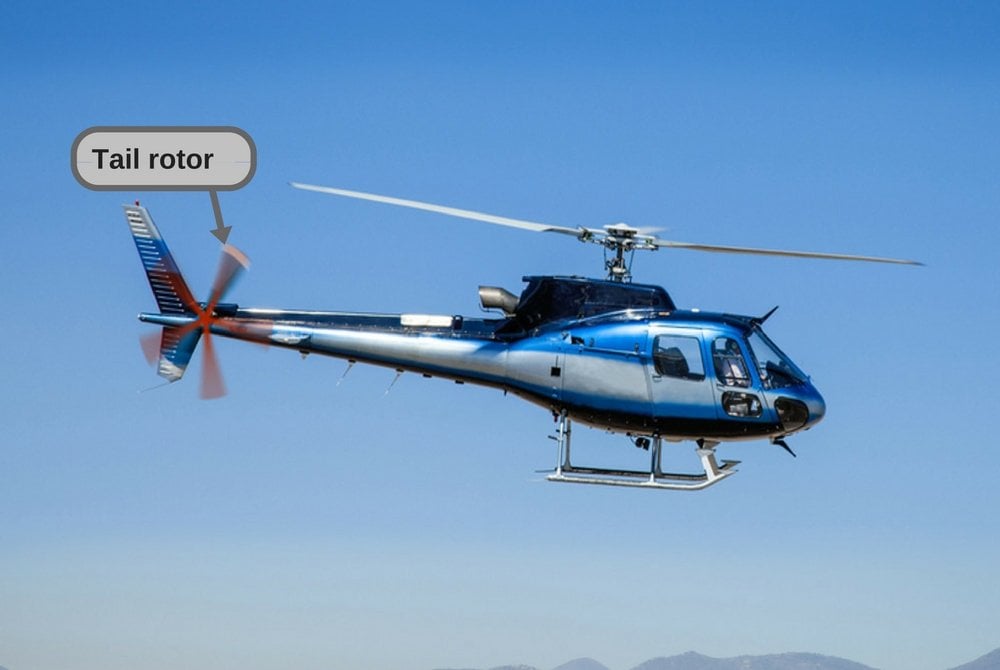
Helicopter in flight. Fly over the mountain and blue sky.


SHORT ANSWER-The tail rotor is there to make sure that the helicopter doesn’t simply fly in circles. Yes, it also helps to turn the helicopter.

Flight of a Helicopter

A helicopter flies/hovers by generating lift with its main rotors. The rotating blades push the air down, which in turn pushes the helicopter up, keeping the entire craft airborne. However, there’s one important catch here…

When the fuselage starts to rotate…

According to Newton’s third law of motion, for every action, there is an equal and opposite reaction. What this means is that when you apply a force on a body in a given direction, that body applies an equal amount of force on you, and in the direction opposite to your application of force. There are numerous practical examples of this phenomenon: the recoil of a gun, the launch of a rocket, how that same rocket turns in space, lifting heavy weights… the list is endless.

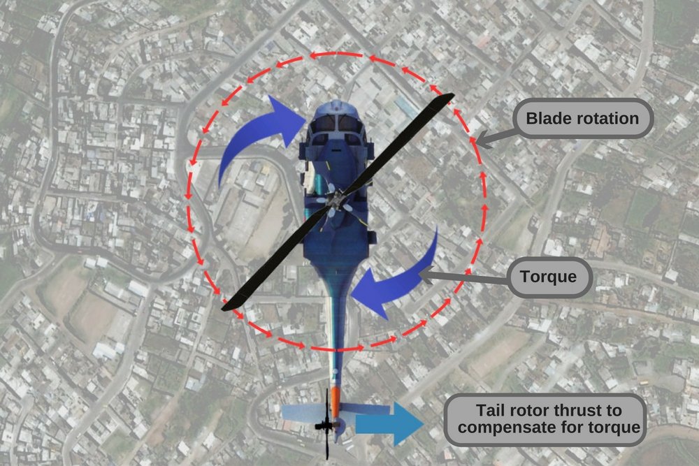
Torque

Helicopter tail rotor blade rotation torque
Applying the third law of motion to the case of helicopter rotors, you would see that since the main rotors turn, say, counter-clockwise, the fuselage (the body of the chopper) would be pushed in a clockwise direction. Simply put, the helicopter would turn in circles in the opposite direction of the blades’ rotation.
Let me illustrate this with an example: sit in a swivel chair and don’t let your feet touch the ground. Now, try to rotate the chair counter-clockwise. You would notice two things: one, it’s much more difficult than you first imagined; and two, you’d be turning clockwise, despite trying to turn in the opposite direction.
Essentially, the same thing happens with a helicopter, where the main rotors, while turning in one direction, push the fuselage the opposite way. Looking at a helicopter that’s turning in circles (some sight that would be!), a physicist would immediately note that it’s rotating due to ‘torque’, a twisting force that causes an object to rotate.

The role of the tail rotor

Countering the torque

tail rotor
Traditional tail rotor of an Aérospatiale Puma
The tail rotor is a vertical (or near-vertical) set of blades mounted at the end of the tail of the chopper. It ensures that the torque produced by the main rotors is properly compensated for by ‘pushing’ the chopper in the opposite direction of the torque. By doing this, it ensures that the chopper doesn’t wobble and remains stable in flight. This is why a helicopter is in serious trouble if its tail rotor is damaged.
Caption: Notice that the chopper comes spiraling down once its tail rotor is hit (Image of  ARMA 2, the video game)
Furthermore, the tail rotor’s position and distance from the center of gravity of the chopper provides thrust in the same direction as the main rotor.
It should be noted that using a tail rotor is not the only way to compensate for the torque; coaxial rotors can also achieve the same thing.
coaxial rotors
Russian Air Force Ka-52, a chopper with two main rotors and no tail rotor 

Turning the chopper

In addition to counteracting the torque produced by the main rotor, the tail rotor can also be used to turn the chopper in a desired direction by altering the pitch angle of the rotor blades. Directional control is achieved by the pilot when he changes the pitch of the blades using anti-torque pedals, which are installed in the cockpit.
There are certain drawbacks of tail rotors, such as making the chopper louder and using up some of the available engine power that could be used to generate lift. While both of these problems are accounted for in choppers with coaxial rotors, those variants have their own disadvantages too. In effect, whether you want to use a conventional helicopter with a tail rotor or a chopper with multiple rotors depends entirely on your operational requirements. Either way, be safe up there!

Monday, 19 December 2016

Why Do Hard Drives/USB Drives Show Less Space Than Advertised When Plugged In?

When I bought my first USB flash drive a few years ago (2 GB), I was rather shocked to see that it only showed 1.95 GB as my total available space. Feeling robbed of the remaining 0.5 GB by the manufacturer, I looked it up on the Internet and found (admittedly, to my relief) that every other hard drive user had the same concern.
You can see this for yourself right now. Take any digital storage device (e.g., USB flash drive, hard drive, SD card etc.) and plug it into a Windows computer. You will notice that the total available space displayed on the computer is slightly less than the advertised capacity of the device. For instance, if you plug in a 16 GB USB drive, the total available space on a Windows computer would be around 15.6 GB – around 0.4 GB short of the advertised capacity.
Why does this happen? Why do Windows devices and some older versions of MacOS show a total available space that is different from what’s advertised? Some people might claim that this is a classic example of false advertising by marketers, or that the manufacturers are purposely lying about the capacity of hard drives, but is that really the truth?
Short answer: Common programs, including Windows, system BIOS and some old versions of MacOS, use the binary number system, where 1 GB amounts to 1024 MBs, rather than 1000 MBs, which leads to this anomaly in storage devices.
Before trying to understand the reason behind this anomaly, it’s important to know a thing or two about MBs, GBs and TBs – the units used to express the capacity of storage devices of different types.

Understanding the basics: kB, MB and GB

The smallest entity used to measure the capacity of storage devices is a rather aptly named unit called a ‘bit’. A sequence of 8 bits make up a ‘byte’; it is this sequence of 8 bits that is processed as a single unit of information. A cluster of 1000 bytes makes up a kilobyte (kB).
but-everyone-says-meme
Many people might tell you that 1 kB has 1,024 bytes, and not 1,000 bytes, and that you should get your computer basics straight. However, those people are confused, just like millions of other computer users all over the world.

Decimal system vs. Binary system

Note that the amount of disk space consumed by a file depends on the file system itself. Now, many popular programs and operating systems, including Microsoft Windows (the most commonly used operating system for computers), system BIOS, FDISK and even some old versions of macOS follow the binary numbering system (with base 2). There is a reason behind that too, but for the scope of this article, suffice to say that it’s convenient within the computer to organize things in groups of powers of 2. Therefore, 1 kB contains 2^10 = 1024 bytes.
However, there’s a catch…. the metric prefixes (e.g., kilo, mega, giga) that we use for measuring the storage capacity of hard drives are all decadic, meaning that they are all expressed as powers of 10 (and not 2).
This prefix system is great for the decimal system, but in a binary system – the one that Windows and many other programs use – the terms kilo, mega, giga etc. do not even exist. Since they work with powers of 2, they use slightly different prefixes to express large numbers. For example, 1024 bytes make up 1 kibibyte, which is represented as KiB. Similarly, 1024 kibibytes make up 1 Mebibyte (MiB). Below is a table to help you understand this better:
Multiples of bytes table
A lot of confusion between the true storage capacity of a device stems from the way these units are commonly written or printed. People mistakenly use the units of the decimal and binary system interchangeably. For example, the unit ‘KiB’ is casually written as ‘KB’ and is therefore mistaken for ‘kilobytes’, but it actually represents ‘kibibytes’. The same goes for MiB and MB (mebibytes and megabytes) and TiB and TB (tebibytes and terabytes).

Do manufacturers falsely label their storage devices to show more capacity?

That answer is a big NO.
manufacturers-always-fool-custo-meme
It is the manufacturers (and not programs like BIOS, Windows etc.) that correctly use the prefix mega and giga, i.e., they use the powers of 10 to express storage capacities when labelling their products.
Take a look at this picture of the back side of the packet of a USB flash drive that I recently bought:
pendrive-cover1
Notice that it clearly mentions on the cover that 1 GB = 1,000,000,000 bytes. The best way to check the true capacity of your drive is to check the number of ‘bytes’, rather than MBs and GBs, as the latter could be somewhat confusing. For manufacturers, 1 MB is 1000 kB , but for Windows, 1 MB is 1024 KB (which is actually 1024 kibibytes). This is why, when you plug a storage device into a Windows computer, the total available space appears slightly less than what’s advertised.
Below is a table showing the anomalies in storage capacity as they appear on Windows:
Windows output (Binary)
Note that Windows could update their user interface and simply use the decimal system to display total capacity. That’s what Apple’s OS X has already done.
The next time you buy a storage device, such as an external hard drive, for your computer and notice that its available space is less than the space advertised on its packaging, don’t fret. Just check the packaging and verify whether its capacity is 2 TB or 2 TiB. Better still, check the number of ‘bytes’ that the hard drive can handle. At that point, you can easily calculate its correct total capacity. Also, if it’s a Windows machine that you’ve plugged it in, it’s bound to show less space than what’s printed on the cover. However, don’t jump to the conclusion that you’ve been cheated out of those 50 GBs by the manufacturer – they’re just trying to be honest!

Friday, 16 December 2016

How Does Wireless Inductive Charging Work?

Back in the day, when smartphones were not as ubiquitous as they are today, people relied on clunky telephones that only had two vital components – the dialer and the handset. In those days, people probably didn’t take the idea of a portable telephone that could be toted around in their pockets very seriously… it would have sounded like science fiction!
you-didnt-need-a-smartphone-to-poop-meme
Fast forward to today, where it would be an uphill task to find someone who doesn’t carry a phone everywhere they go. However, a very common issue with smartphones is battery drain – their tendency to discharge their stored energy quite rapidly. Although recharging phones through wired adapters is still the most commonly seen method, wireless charging has signaled a new era of recharging phones’ batteries without the need for wires. In this article, we are going to look at how wireless charging works and whether it is safe.

Inductive charging

More commonly referred to as ‘wireless charging’, inductive charging works on the same principle as induction cooktops – electromagnetic induction, or simply induction.
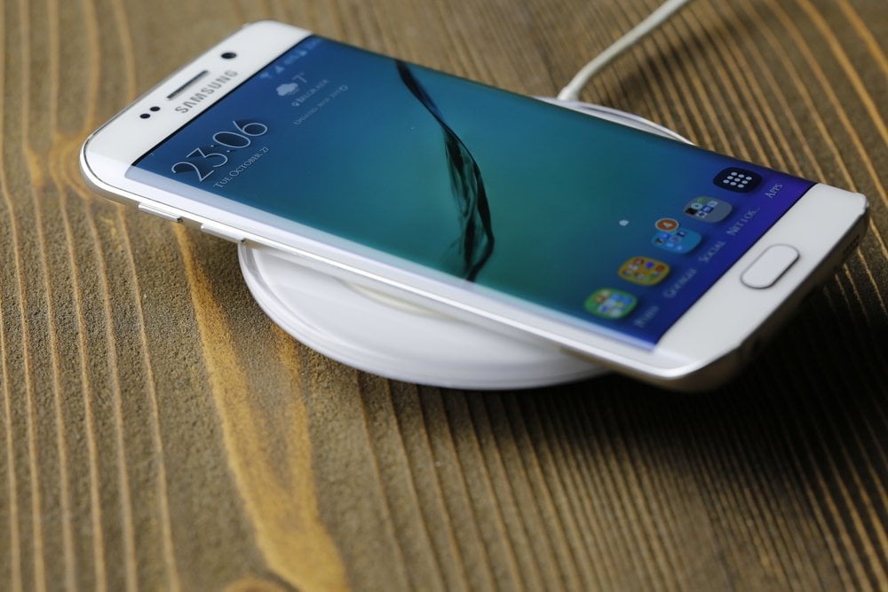
smartphone inductive charging using a mat
A smartphone placed on a base plate for inductive charging (Photo Credit : Nebojsa Markovic / Shutterstock)
Electromagnetic induction results in the production of voltage across a conductor placed in a changing magnetic field or a conductor moving through a stationary magnetic field.

How does inductive charging work?

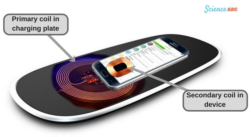
Induction chargers consist of two primary induction coils. One is housed in the ‘charging base’ (commonly known as the ‘mat’) and is responsible for generating an alternating current (AC) from within the base. The other is in the portable device in need of a charge (like a smartphone, tablet etc.). The coil might be in the form of a pad that clips to your phone, a circuit embedded inside your phone, or a replacement battery cover with a built-in charging coil that gets connected to the charging socket. Together, these two coils make up an electrical transformer.
Mobile wireless chargning
When the power supply to the charging base/plate is switched on, AC flows through it and creates an electromagnetic field (a changing magnetic field) around the primary coil. When the secondary coil (the receiver coil, which is housed in the smartphone) comes in close proximity to the former, an electric current is generated within the coil. The AC flowing through the coil in the smartphone is converted into DC (Direct Current) by the receiver circuit. The DC generated in this way could ultimately be used to charge the battery of the smartphone.

Advantages and Drawbacks

One of the biggest advantages of inductive charging is that it’s wireless, so you don’t have to deal with all those tangled cables. Furthermore, its connections are all enclosed and thus protected, so you run a much smaller risk of electric faults.

if-inductive-charging-is-so-good-meme
There are a few reasons behind that. The biggest drawback of inductive charging is its low efficiency, as a great deal of energy is lost as heat. As a result, your device takes much longer than usual to charge. Furthermore, it’s more expensive than your regular wired chargers.
Some people find it a little inconvenient too, as you have to keep your device on the mat the whole time that it’s being charged. Therefore, you don’t have the luxury to use it while it’s being charged. However, this has been taken care of by WiTricity’s wireless chargers, which can charge your phone from a distance.

Are inductive wireless chargers safe?

We have a tendency to be scared of anything that emits ‘waves’ and ‘signals’, and we invariably presume that they must be harmful to us in some way (like a microwave oven, WiFi router, and even smartphones). However, like most of the things listed here, inductive chargers are absolutely safe.
safer-than-regular-smartphone-chargers-even-meme
The electromagnetic field that an inductive charger creates is not strong enough to do any harm to humans. In fact, these chargers might even be safer than the regular ones, since they don’t operate with any wires, which means that you’re protected from even the tiniest chances of sustaining an electrical shock.
Eminent scientist Nikola Tesla pioneered the idea in the late 1800s that power could be transmitted through an electromagnetic field between two objects. In effect, he had envisioned the concept of inductive charging almost two centuries before it came into existence. No wonder he’s dubbed ‘the man who invented the 20th century’!